Retrofit Skywatcher Motorised Focuser To Bresser Newtonian Telescope
One of the problems with the manual focusers on the telescope is it can cause the scope to wobble, which is really annoying while trying to focus on an object.
To combat this wobble, and achieve a hands off focus, I decided to get my hands on a motorised focuser. Now these can be ridiculously expensive, but Skywatcher do a relatively cheaper version.
Having received it from the telescope shop in Nicosia, 1010 Asteroskopeion, I took a look at how it was going to connect, and what I need to make it fit.
Here is what the base of the telescope focuser looks like.
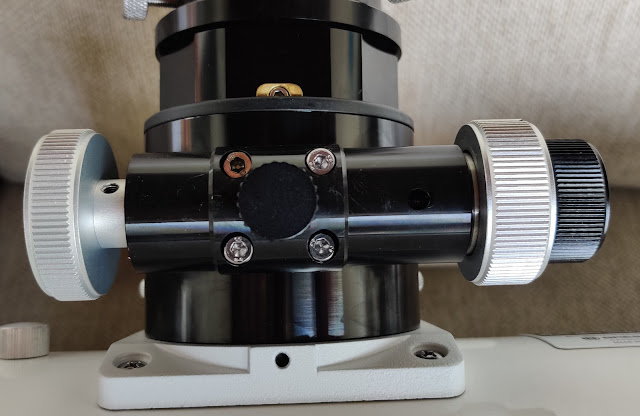
On the right hand side, the focus adjuster is a 10:1 HexFocus modification that I added when I first got the scope, it really made a difference compared to the standard adjuster, I want to retain it in place, therefore on the left is the existing focuser knob that will be removed and replaced by the motor.
The problem is as you can see below, the brackets provided, don't line up with the holes on the rack and pinion mount. There is also a rack locking pin in the centre, and need to cater for it just in case I ever need it.

I took a vernier caliper and started to measure various dimension, the bolts positioning, the length of the focuser section etc. made a very rough sketch, and then modelled on on Tinkercad.

Having printed out the Version 1, I then tried to fit it onto the focuser. This didn't go too smoothly;
First up I removed the screws and the focuser lock and placed the printed part, and secured into place. You need to be careful as the locking clamp can slide out from underneath if you lift of the rack and pinion assembly.
The existing hex head bolts were too short, and with the current lockdown, unable just to nip to the DIY shop to see what they have. After poking around in my various boxes, I found that some spare cupboard door handle screws were the same thread and of suitable length.

Reinstated the focuser locking knob and attached the flexible coupling in place of the focuser knob.

Attached the supplied bracket into appropriate holes, having first lined up where the motor will sit to get the correct spacing at the coupler. I found some old coarse thread screws that I had ripped out an old printer some time ago.

Finally, attached the motor, and literally took it for a spin. It works, although it's not pretty. You can see a slight layer separation between the left and right half of the piece.


I don't like the coupler as the way the grub screws lock, it is off centre slightly at the motor end, so it does not look right as it rotates. Maybe knock up a custom one at a later date.
Here is the link to the model and the view of the model below.
https://www.tinkercad.com/things/8HjqCmjzN23
That it then, no more jiggly manual focusing!
Going to leave everything as is having found that out!

To combat this wobble, and achieve a hands off focus, I decided to get my hands on a motorised focuser. Now these can be ridiculously expensive, but Skywatcher do a relatively cheaper version.
Having received it from the telescope shop in Nicosia, 1010 Asteroskopeion, I took a look at how it was going to connect, and what I need to make it fit.
Here is what the base of the telescope focuser looks like.

On the right hand side, the focus adjuster is a 10:1 HexFocus modification that I added when I first got the scope, it really made a difference compared to the standard adjuster, I want to retain it in place, therefore on the left is the existing focuser knob that will be removed and replaced by the motor.
The problem is as you can see below, the brackets provided, don't line up with the holes on the rack and pinion mount. There is also a rack locking pin in the centre, and need to cater for it just in case I ever need it.

I took a vernier caliper and started to measure various dimension, the bolts positioning, the length of the focuser section etc. made a very rough sketch, and then modelled on on Tinkercad.

Having printed out the Version 1, I then tried to fit it onto the focuser. This didn't go too smoothly;
- Only 2 of the mount screws are used, the other 2 do not go into the focuser, but appear to be for alignment of the rack and maintain correct tension. I managed to crack the print, due to trying to force something that was never going to go!
- Drilling the top of the printed piece turned into a mess due to the PLA melting and binding.
Version 2
I made some amendments to the model, and printed out Version 2. The changes included;- Added some curved sections to sit better on the profile of the focuser.
- Change to the hole configuration to account for the heads of the bolts that do not fully insert.
- Made some holes to account for different position on the provided brackets.
- Adjust the hole diameters to make it better clearance,
- Dremel out the curved profile as one of the length was slightly short.
- Dremel out some additional clearance for the 2x bolt heads that are for alignment.
First up I removed the screws and the focuser lock and placed the printed part, and secured into place. You need to be careful as the locking clamp can slide out from underneath if you lift of the rack and pinion assembly.
The existing hex head bolts were too short, and with the current lockdown, unable just to nip to the DIY shop to see what they have. After poking around in my various boxes, I found that some spare cupboard door handle screws were the same thread and of suitable length.

Reinstated the focuser locking knob and attached the flexible coupling in place of the focuser knob.

Attached the supplied bracket into appropriate holes, having first lined up where the motor will sit to get the correct spacing at the coupler. I found some old coarse thread screws that I had ripped out an old printer some time ago.

Finally, attached the motor, and literally took it for a spin. It works, although it's not pretty. You can see a slight layer separation between the left and right half of the piece.

Version 3
Subsequently I made some further changes in Version 3, printed out and fitted that, it is almost there, just need to modify slightly to accommodate the heads for the bolts that are hidden underneath, i.e. the ones that are not visible, but the adjustment holes are. The layer lines now run left to right, compared to the photo above that is top to bottom.
I don't like the coupler as the way the grub screws lock, it is off centre slightly at the motor end, so it does not look right as it rotates. Maybe knock up a custom one at a later date.
Version 4
Version 4 is not printed yet, it also includes a small cylinder that can be popped into the locking pin hole to raise the locking knob out a bit. Version 4 is the one that is live on the Tinkercad model at time of writing this.Here is the link to the model and the view of the model below.
https://www.tinkercad.com/things/8HjqCmjzN23
That it then, no more jiggly manual focusing!
Update: 01-Apr-20
I have found that I couldn't manually focus using the focus knobs with the motor setup, so had considered moving the motor to the inboard other side of the scope and removing the 10:1 focus knob altogether. However, I disconnected only the cable from the motor's focus handset, and found the manual focus works fine. So there must be a downside to keeping the focus handset plugged in all the time, when the scope is not in use. Motor must be held in position when plugged in.Going to leave everything as is having found that out!
Update 02-Apr-20
I had a flash of inspiration today, and thought, what about if I unscrew the the two screws that hold the adjustment assembly onto the scope, and rotate it 180', now the motor will be inbound, and the manual adjuster will be outbound and look a lot tidier and easier to use/store etc. Can it be that simple? Well, yes as it it turns out.


Comments
Post a Comment