Building OpenVPN Site-To-Site Tunnel on Dynamic Addressing Endpoints
Note: I originally published this article in October 2016 on CodeProject. The original article can be found at: https://www.codeproject.com/Articles/1135556/Building-OpenVPN-Site-To-Site-Tunnel-on-Dynamic-Ad
In this article we will take a look at how I implemented a OpenVPN tunnel to allow access to my home network in Scotland for gaining access to my CCTV system and NAS boxes and allow the Smart TV etc. to think they were still located in Scotland, but why would we need to do that! Network restrictions will not get in between the wife and her Great British Bake Off!
It wasn't a smooth ride to get there, but took many trial and error attempts and lots of article reading to get my head round it all and fit all the pieces together.
In Qatar, I am on a FTTH connection and have a 100Mbs link (upgradeable to 1Gbs should the need, and money, be there!) and again this was on a Dynamic Address and the second problem was that there was a Q-Tel Fibre Gateway that could not be replaced and all traffic had to come through this. The other big challenge in Qatar is the building, it is solid concrete walls. the existing cable conduits in the wall are a bit hit and miss, some of them are blocked, and they don't go where you want them to! Wifi doesn't penetrate well so lots of extenders needed to reach everywhere.
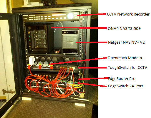
I had completely rebuilt my network at home and packed it into a network rack. The network was also split into a few different subnets for main network, CCTV and Wifi, It consists of;
Here is what the rack looks like:
Q-Tel Fibre Gateway:

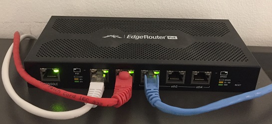
EdgeRouter POE:
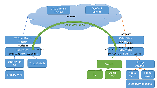
What we are ultimately aiming for is the following setup:
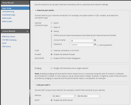
Basic setup wizard screen in the EdgeRouter Pro:
Before leaving the UK, I had to make sure I had access to my router. To do this the first thing was to open up the RemoteGUI port in the firewall rules. Using the GUI It was simply a case of adding a rule to the WAN_LOCAL ruleset for port 443 and allowed both TCP and UDP traffic.
Firewall rule configuration on the EdgeRouter Pro:

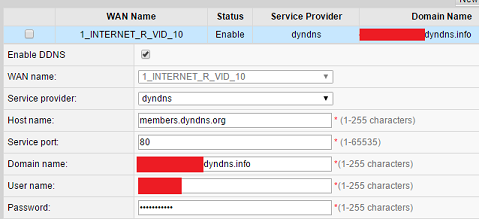
Fortunately both of these devices (EdgeRouter Pro and Q-tel) had inbuilt support for DynamicDNS services. The EdgeRouter supported more providers, but they both support DynDNS. I registered for the service, and set up two domains, one for each end.
This information was then entered on the EdgeRouter,the interface is simply which port on the router had the dynamic address to monitor for changes;

When I arrived in Qatar, I configured the fibre gateway for the other DynDNS address;
For the purposes of this article, let us call the two endpoints router1.dyndns.info and router2.dyndns.info
The Q-Tel gateway has multiple functionality, it supported Internet, Voice and IP TV and that is why there was a strange WAN name configured on the box.
I could always go back and establish some specific port forwarding rules at a later date, but for the time being I was happy that the firewall on the ER-POE should do its stuff just fine.
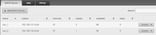
I created two DHCP services on the ER-POE, one to server Lan1 address range 192.168.101.0/24 and a second for the Lan2 on 192.168.102.0/24
Now I had two routers that were remotely accessible and using DynamicDNS for their endpoints I could carry out a bandwidth test between the two of them.
The EdgeRouters have iPerf3 built into the firmware, and they provide a GUI wrapper for some of the basic functions from the web interface, but this doesn't really give much away and I have found it to be a bit flaky and prefer to use the command line interface via the web interface.
To facilitate this testing I need to open up the firewalls on both machines for port (can be changed if you wish) 5201
On the far end (Router1), I set this up as the 'Server' using;
iperf3 -s
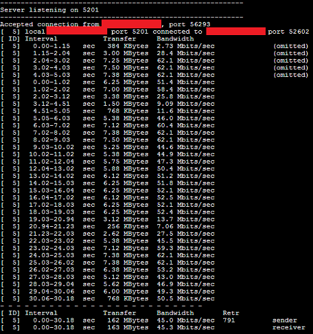
On the near end (Router2), I issue the following command which runs in 'Client' mode, for 30 seconds and ignores the first 5 seconds to allow the connection time to spool up.
iperf3 -c router1.dyndns.info -t 30 -O 5
Both consoles will start to output current transfer rates etc. and then output an overall test speed. I found that this can be very variable depending on time of day. This is very typical and I often see drop outs late afternoon early evening in Qatar. However, the example below was when the article was written and not at the actual time I did the initial testing. The output shows that at this time it was around 45Mbs. which isn't too bad considering I am crossing public internet and on residential lines and the distance between the two sites is 5,503 km (based on my lightning detector GPS sensors).
generate vpn openvpn-key /config/auth/secret
Next was to transfer the secret key across to the Router2. I tried copying and pasting via a Notepad session, but was always told that the key was corrupt. In the end I opened up SSH port 22 and pushed the key file across to Router2 using;
sudo scp /config/auth/secret username@router2.dyndns.info:/config/auth/secret
and entering the password when prompted.
On Router1 the following commands where entered;
Enter configuration mode:
configure
Define tunnel interface and the mode of operation:
set interfaces openvpn vtun0
set interfaces openvpn vtun0 mode site-to-site
Assign the ports (you can change these should you wish, just make the firewall match):
set interfaces openvpn vtun0 local-port 1194
set interfaces openvpn vtun0 remote-port 1194
Next was to assign the address for the tunnel endpoints, this must not be part of any existing subnets on the network and then the public address of the remote tunnel endpoint:
set interfaces openvpn vtun0 local-address 10.99.99.1
set interfaces openvpn vtun0 remote-address 10.99.99.2
set interfaces openvpn vtun0 remote-host router2.dyndns.info
Configure the secret key to use and the compression algorithm for the link:
set interfaces openvpn vtun0 shared-secret-key-file /config/auth/secret
set interfaces openvpn vtun0 openvpn-option "--comp-lzo"
Now configure the last of the options for OpenVPN:
set interfaces openvpn vtun0 openvpn-option "--float"
set interfaces openvpn vtun0 openvpn-option "--ping 10"
set interfaces openvpn vtun0 openvpn-option "--ping-restart 20"
set interfaces openvpn vtun0 openvpn-option "--ping-timer-rem"
set interfaces openvpn vtun0 openvpn-option "--persist-tun"
set interfaces openvpn vtun0 openvpn-option "--persist-key"
set interfaces openvpn vtun0 openvpn-option "--user nobody"
set interfaces openvpn vtun0 openvpn-option "--group nogroup"
Now we must configure the remote subnet the tunnel endpoint resides and which interface to use:
set protocols static interface-route 192.168.101.0/24 next-hop-interface vtun0
Finally, we commit the changes:
commit
save
exit
Do the same again for Router2, and
Enter configuration mode:
configure
Define tunnel interface and the mode of operation:
set interfaces openvpn vtun0
set interfaces openvpn vtun0 mode site-to-site
Assign the ports (make sure the same as you put in Router 1):
set interfaces openvpn vtun0 local-port 1194
set interfaces openvpn vtun0 remote-port 1194
Next was to assign the address for the tunnel endpoints, this must not be part of any existing subnets on the network and then the public address of the remote tunnel endpoint:
set interfaces openvpn vtun0 local-address 10.99.99.2
set interfaces openvpn vtun0 remote-address 10.99.99.1
set interfaces openvpn vtun0 remote-host router1.dyndns.info
Configure the secret key to use and the compression algorithm for the link:
set interfaces openvpn vtun0 shared-secret-key-file /config/auth/secret
set interfaces openvpn vtun0 openvpn-option "--comp-lzo"
Now configure the last of the options for OpenVPN:
set interfaces openvpn vtun0 openvpn-option "--float"
set interfaces openvpn vtun0 openvpn-option "--ping 10"
set interfaces openvpn vtun0 openvpn-option "--ping-restart 20"
set interfaces openvpn vtun0 openvpn-option "--ping-timer-rem"
set interfaces openvpn vtun0 openvpn-option "--persist-tun"
set interfaces openvpn vtun0 openvpn-option "--persist-key"
set interfaces openvpn vtun0 openvpn-option "--user nobody"
set interfaces openvpn vtun0 openvpn-option "--group nogroup"
Now we must configure the remote subnet the tunnel endpoint resides and which interface to use:
set protocols static interface-route 192.168.0.0/24 next-hop-interface vtun0
Finally, we commit the changes:
commit
save
exit
All going well, this will initiate and open the tunnel.
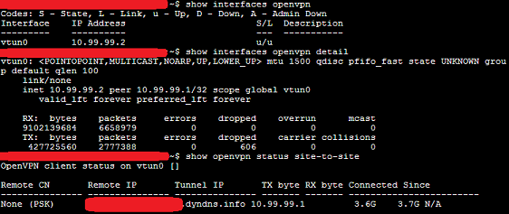
The tunnel status can be checked using the following commands from either routers command line console:
show interfaces openvpn
show interfaces openvpn detail
show openvpn status site-to-site
If for any reason you need to force a restart of the tunnel, this is achieved by:
restart openvpn interface vtun0
I only want the traffic that sits on the 192.168.101.0/24 subnet to be put across the tunnel. To achieve this we need to use Source Address Firewall Modification rules.
Note: For the next part I actually manually edited by hand the config file and then uploaded it back into the router, but the commands should be the ones below!
The first part of this process is to define two new routing tables (don't forget to enter configure mode):
configure
set protocols static table 1 route 0.0.0.0/0 next-hop-interface eth0
set protocols static table 2 route 0.0.0.0/0 next-hop-interface vtun0
Now we create the two rule sets to use these two tables and route the traffic:
set firewall modify SOURCE_ROUTE rule 10 description 'Traffic to internet'
set firewall modify SOURCE_ROUTE rule 10 source address 192.168.102.0/24
set firewall modify SOURCE_ROUTE rule 10 modify table 1
set firewall modify SOURCE_ROUTE rule 20 description 'Traffic to tunnel'
set firewall modify SOURCE_ROUTE rule 20 source address 192.168.101.0/24
set firewall modify SOURCE_ROUTE rule 20 modify table 2
Apply the changes to the internal interface;
set interfaces eth1 firewall in modify SOURCE_ROUTE
commit
save
Now, that should be all good, with only the IP addresses in the subnet 192.168.101.0/24 being routed across the VPN tunnel.
Hooking up a laptop to the ports eth1 and the switched port eth2, eth3, eth4 and obtaining an address by DHCP we could now test the routing. the best way to do this was simply to go to google and type in "Where am I", you would be presented with a map which changed depending on which port you were on....success! Of course, the REAL test was BBC iPlayer....but we won't go into that ;-)
To test the tunnel, we open up the server at the far end in the same way as before, but at the local end, this time we tell it to connect to the remote end point of the tunnel
iperf3 -c 10.99.99.1 -t 30 -O 5

DHCP Bridging - it should be possible to have the DHCP addresses allocated by the remote DHCP server.
Performance - I could play around with the different compression algorithms and see which one is the quickest.
Protocols - I could look at changing from TCP to UDP for the tunnel and see how that changes the performance.
However, the link is working, is stable and is currently meeting my needs.......so why mess about with it and risk breaking it at the stage.
OpenVPN wasn't the first protocol I had tried. I had originally looked at L2TP/IPSec (Layer 2 tunnelling protocol/IP Security) and even tried to follow the video tutorial, but that was just a complete no go. I don't know if it was the additional complications of the Q-Tel router, or the Dynamic addressing, but it just wouldn't work. (https://help.ubnt.com/hc/en-us/articles/204959404-EdgeMAX-Set-up-L2TP-over-IPsec-VPN-server)
Another interesting thing was the television, a UK model Samsung, the link died one day when the internet appears to have gone belly up, and no matter what I did, it wouldn't recover. In the end, I had to factory reset the TV and when the SmartHub functions started up, it was all in Arabic, with no option to change. Fixing the link and proving it was working with my laptop, then factory reseting the TV again, this time the TV came up in English and allowed me to install the regionally aware apps.
I am sure I had an issue with the DNS configuration originally, which meant it was picking up some cached names on the router, only once I had removed the DNS forwarding for the interface and reconfigured the DHCP to issue the Google DNS IPs instead of the router interface, all was good.
The biggest headache was the cabling. I had originally tried to pull in cat-5 through a few different conduits, but without success. in the end I used Powerline AV adapters to the perform a hop across the ground floor, then a second pair of Powerline AVs to hop across the upstairs floor to where the network gear is.
Overall, this has been an interesting little 'project'........and satisfied with the outcome. I have to admit that the Ubiquiti hardware has been the best networking products I have had to date particularly. They continue to extend the GUI functionality, and there is still a lot you cannot do unless you delve into the command line. I guess finding the balance between 'pretty' and 'functional', a bit like Windows and Powershell!
Time will tell to see how this performs, but so far so good. It has only really been about 4 weeks, and only had one failure, that was with the incorrect DNS configuration. Hopefully that has now been amended, things should be rock solid now.
Introduction
Back in 2015 after over 25 years of playing in the Oil Industry in the North Sea living in the 'Silver City' and working on the oil platforms in the Forties Field and Beryl Field, I uprooted my family from the very changeable climate of Scotland and headed out to the searing heat and sandy environment of Qatar to work in the Al-Shaheen Field.In this article we will take a look at how I implemented a OpenVPN tunnel to allow access to my home network in Scotland for gaining access to my CCTV system and NAS boxes and allow the Smart TV etc. to think they were still located in Scotland, but why would we need to do that! Network restrictions will not get in between the wife and her Great British Bake Off!
It wasn't a smooth ride to get there, but took many trial and error attempts and lots of article reading to get my head round it all and fit all the pieces together.
The Challenges
In Scotland, I was running on an BT Infinity connection which was stable around 65Mbs/18Mbs Down/Up. I had replaced the BT provided HomeHub router as it was just horrendous and had a device count limitation in the DHCP addressing. It topped out at 20 devices, which was no use in my household! After sometime, my network in the house was starting to get a bit heavy and needed a big revamp. You can see what the before was like in my CCTV article here: https://www.codeproject.com/Articles/768867/Ive-Got-My-Eye-On-You-A-Journey-Into-Home-CCTV, but we will get onto the hardware later. The main challenge at the UK end was that the BT connection was a Dynamic Address and regularly changed.In Qatar, I am on a FTTH connection and have a 100Mbs link (upgradeable to 1Gbs should the need, and money, be there!) and again this was on a Dynamic Address and the second problem was that there was a Q-Tel Fibre Gateway that could not be replaced and all traffic had to come through this. The other big challenge in Qatar is the building, it is solid concrete walls. the existing cable conduits in the wall are a bit hit and miss, some of them are blocked, and they don't go where you want them to! Wifi doesn't penetrate well so lots of extenders needed to reach everywhere.
The Hardware
Scotland End
I had completely rebuilt my network at home and packed it into a network rack. The network was also split into a few different subnets for main network, CCTV and Wifi, It consists of;
- Ubiquiti Edgerouter Pro
- Ubiquiti EdgeSwitch 24
- Ubiquiti ToughSwitch (for CCTV Subnet)
- Ubiquiti UniFi AC AP
- BT OpenReach Modem
Here is what the rack looks like:
Qatar End
This end was a lot simpler, it simply consisted of;- Ubiquiti EdgeRouter POE
- Q-Tel Fibre Gateway
- LinkSys AC2600 Router
- Bunch of Wifi Extenders and Powerline Adaptors
Q-Tel Fibre Gateway:
EdgeRouter POE:
What we are ultimately aiming for is the following setup:
Configuration Time
We are not going to go into every configuration part. The Ubiquiti routers have a couple of basic wizards that get them up and running as basic routers with default firewall rules etc. This article is focusing on getting the tunnel up and running and the necessary routing at the Qatar end to determine where the devices on the network should send the traffic to.Basic setup wizard screen in the EdgeRouter Pro:
Remote Access Configuration
Before leaving the UK, I had to make sure I had access to my router. To do this the first thing was to open up the RemoteGUI port in the firewall rules. Using the GUI It was simply a case of adding a rule to the WAN_LOCAL ruleset for port 443 and allowed both TCP and UDP traffic.Firewall rule configuration on the EdgeRouter Pro:
Dynamic DNS
I also had to set-up the DynamicDNS for dealing with the dynamic nature of the endpoints. Both UK and Qatar had ISP supplied dynamic addresses, and both of these changed quite frequently.Fortunately both of these devices (EdgeRouter Pro and Q-tel) had inbuilt support for DynamicDNS services. The EdgeRouter supported more providers, but they both support DynDNS. I registered for the service, and set up two domains, one for each end.
This information was then entered on the EdgeRouter,the interface is simply which port on the router had the dynamic address to monitor for changes;
For the purposes of this article, let us call the two endpoints router1.dyndns.info and router2.dyndns.info
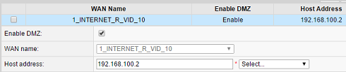
Establishing a DMZ (demilitarized zone)
The Q-tel box was a bit of a pain, and right at the start I still wasn't sure what ports I was going to need to establish as I still hadn't worked out how I was going to link the two sites. It was easier just to setup a DMZ and route all traffic to the inner router (i.e. the EdgeRouter POE) and let it deal with all the firewall policies and routing. I had configured it (ER-POE) with a static address 192.168.100.2 and its internet port was connected to one of the ethernet ports on the Q-tel gateway. The Q-Tel box itself defaulted to 192.168.100.1, hence the reason for the address selected on the ER-POE.The Q-Tel gateway has multiple functionality, it supported Internet, Voice and IP TV and that is why there was a strange WAN name configured on the box.
I could always go back and establish some specific port forwarding rules at a later date, but for the time being I was happy that the firewall on the ER-POE should do its stuff just fine.
EdgeRouter POE Initial Configuration
Again there was a basic wizard that could be applied that put the 'Internet' on Eth0, Lan1 on Eth1 and then Lan2 switched on Eth2, Eth3 and Eth4. Eth0 was connected to the Q-Tel and was configured for the static address 192.168.100.2I created two DHCP services on the ER-POE, one to server Lan1 address range 192.168.101.0/24 and a second for the Lan2 on 192.168.102.0/24
Initial Bandwidth Testing
Now I had two routers that were remotely accessible and using DynamicDNS for their endpoints I could carry out a bandwidth test between the two of them.
The EdgeRouters have iPerf3 built into the firmware, and they provide a GUI wrapper for some of the basic functions from the web interface, but this doesn't really give much away and I have found it to be a bit flaky and prefer to use the command line interface via the web interface.
To facilitate this testing I need to open up the firewalls on both machines for port (can be changed if you wish) 5201
On the far end (Router1), I set this up as the 'Server' using;
iperf3 -s
On the near end (Router2), I issue the following command which runs in 'Client' mode, for 30 seconds and ignores the first 5 seconds to allow the connection time to spool up.
iperf3 -c router1.dyndns.info -t 30 -O 5
Both consoles will start to output current transfer rates etc. and then output an overall test speed. I found that this can be very variable depending on time of day. This is very typical and I often see drop outs late afternoon early evening in Qatar. However, the example below was when the article was written and not at the actual time I did the initial testing. The output shows that at this time it was around 45Mbs. which isn't too bad considering I am crossing public internet and on residential lines and the distance between the two sites is 5,503 km (based on my lightning detector GPS sensors).
Opening the Tunnel
The first part of the tunnel configuration was generating a secret key to use with the link. This was as simple as opening up the CLI console on Router1 and issuing;generate vpn openvpn-key /config/auth/secret
Next was to transfer the secret key across to the Router2. I tried copying and pasting via a Notepad session, but was always told that the key was corrupt. In the end I opened up SSH port 22 and pushed the key file across to Router2 using;
sudo scp /config/auth/secret username@router2.dyndns.info:/config/auth/secret
and entering the password when prompted.
On Router1 the following commands where entered;
Enter configuration mode:
configure
Define tunnel interface and the mode of operation:
set interfaces openvpn vtun0
set interfaces openvpn vtun0 mode site-to-site
Assign the ports (you can change these should you wish, just make the firewall match):
set interfaces openvpn vtun0 local-port 1194
set interfaces openvpn vtun0 remote-port 1194
Next was to assign the address for the tunnel endpoints, this must not be part of any existing subnets on the network and then the public address of the remote tunnel endpoint:
set interfaces openvpn vtun0 local-address 10.99.99.1
set interfaces openvpn vtun0 remote-address 10.99.99.2
set interfaces openvpn vtun0 remote-host router2.dyndns.info
Configure the secret key to use and the compression algorithm for the link:
set interfaces openvpn vtun0 shared-secret-key-file /config/auth/secret
set interfaces openvpn vtun0 openvpn-option "--comp-lzo"
Now configure the last of the options for OpenVPN:
set interfaces openvpn vtun0 openvpn-option "--float"
set interfaces openvpn vtun0 openvpn-option "--ping 10"
set interfaces openvpn vtun0 openvpn-option "--ping-restart 20"
set interfaces openvpn vtun0 openvpn-option "--ping-timer-rem"
set interfaces openvpn vtun0 openvpn-option "--persist-tun"
set interfaces openvpn vtun0 openvpn-option "--persist-key"
set interfaces openvpn vtun0 openvpn-option "--user nobody"
set interfaces openvpn vtun0 openvpn-option "--group nogroup"
Now we must configure the remote subnet the tunnel endpoint resides and which interface to use:
set protocols static interface-route 192.168.101.0/24 next-hop-interface vtun0
Finally, we commit the changes:
commit
save
exit
Do the same again for Router2, and
Enter configuration mode:
configure
Define tunnel interface and the mode of operation:
set interfaces openvpn vtun0
set interfaces openvpn vtun0 mode site-to-site
Assign the ports (make sure the same as you put in Router 1):
set interfaces openvpn vtun0 local-port 1194
set interfaces openvpn vtun0 remote-port 1194
Next was to assign the address for the tunnel endpoints, this must not be part of any existing subnets on the network and then the public address of the remote tunnel endpoint:
set interfaces openvpn vtun0 local-address 10.99.99.2
set interfaces openvpn vtun0 remote-address 10.99.99.1
set interfaces openvpn vtun0 remote-host router1.dyndns.info
Configure the secret key to use and the compression algorithm for the link:
set interfaces openvpn vtun0 shared-secret-key-file /config/auth/secret
set interfaces openvpn vtun0 openvpn-option "--comp-lzo"
Now configure the last of the options for OpenVPN:
set interfaces openvpn vtun0 openvpn-option "--float"
set interfaces openvpn vtun0 openvpn-option "--ping 10"
set interfaces openvpn vtun0 openvpn-option "--ping-restart 20"
set interfaces openvpn vtun0 openvpn-option "--ping-timer-rem"
set interfaces openvpn vtun0 openvpn-option "--persist-tun"
set interfaces openvpn vtun0 openvpn-option "--persist-key"
set interfaces openvpn vtun0 openvpn-option "--user nobody"
set interfaces openvpn vtun0 openvpn-option "--group nogroup"
Now we must configure the remote subnet the tunnel endpoint resides and which interface to use:
set protocols static interface-route 192.168.0.0/24 next-hop-interface vtun0
Finally, we commit the changes:
commit
save
exit
All going well, this will initiate and open the tunnel.
The tunnel status can be checked using the following commands from either routers command line console:
show interfaces openvpn
show interfaces openvpn detail
show openvpn status site-to-site
If for any reason you need to force a restart of the tunnel, this is achieved by:
restart openvpn interface vtun0
Configuring routing across the Tunnel
At the Qatar end Router2, I do not want all traffic to be routed across the tunnel. All normal traffic on the ER-POE would be routed as normal into the internet, i.e. that is all traffic that sits on the 192.168.102.0/24 subnet.I only want the traffic that sits on the 192.168.101.0/24 subnet to be put across the tunnel. To achieve this we need to use Source Address Firewall Modification rules.
Note: For the next part I actually manually edited by hand the config file and then uploaded it back into the router, but the commands should be the ones below!
The first part of this process is to define two new routing tables (don't forget to enter configure mode):
configure
set protocols static table 1 route 0.0.0.0/0 next-hop-interface eth0
set protocols static table 2 route 0.0.0.0/0 next-hop-interface vtun0
Now we create the two rule sets to use these two tables and route the traffic:
set firewall modify SOURCE_ROUTE rule 10 description 'Traffic to internet'
set firewall modify SOURCE_ROUTE rule 10 source address 192.168.102.0/24
set firewall modify SOURCE_ROUTE rule 10 modify table 1
set firewall modify SOURCE_ROUTE rule 20 description 'Traffic to tunnel'
set firewall modify SOURCE_ROUTE rule 20 source address 192.168.101.0/24
set firewall modify SOURCE_ROUTE rule 20 modify table 2
Apply the changes to the internal interface;
set interfaces eth1 firewall in modify SOURCE_ROUTE
commit
save
Now, that should be all good, with only the IP addresses in the subnet 192.168.101.0/24 being routed across the VPN tunnel.
Hooking up a laptop to the ports eth1 and the switched port eth2, eth3, eth4 and obtaining an address by DHCP we could now test the routing. the best way to do this was simply to go to google and type in "Where am I", you would be presented with a map which changed depending on which port you were on....success! Of course, the REAL test was BBC iPlayer....but we won't go into that ;-)
Tunnel Performance
I carried out some further bandwidth tests and managed to achieve around maximum 11 Mbs which is sufficient to watch a streaming movie.To test the tunnel, we open up the server at the far end in the same way as before, but at the local end, this time we tell it to connect to the remote end point of the tunnel
iperf3 -c 10.99.99.1 -t 30 -O 5
What Is Next?
There are a few things that I can continue to investigate,DHCP Bridging - it should be possible to have the DHCP addresses allocated by the remote DHCP server.
Performance - I could play around with the different compression algorithms and see which one is the quickest.
Protocols - I could look at changing from TCP to UDP for the tunnel and see how that changes the performance.
However, the link is working, is stable and is currently meeting my needs.......so why mess about with it and risk breaking it at the stage.
Additional Problem
You may notice in the topology view, that I made reference to 1and1 domain hosting, well this came about because I was at work one day and wanted to remote into the router to check everything was ok. Unfortunately access to the DynDNS domains I had created was restricted. However, I have a few other domains, so simply set up some forwarding subdomains off of one of the these forwarding to the DynDNS domain and problem solved.....References
- iPerf3
- EdgeMAX - Policy based routing (source address based)
- EdgeMAX - OpenVPN Site-to-Site
- The Ubiquit EdgeRouter: Configuring this extremely low-cost, enterprise-grade router for home use
- OpenVPN Manual
Points of Interest
I couldn't believe how difficult it was to get my head round this at the beginning, after all, I hadn't really used the routers to anything other than default setup.OpenVPN wasn't the first protocol I had tried. I had originally looked at L2TP/IPSec (Layer 2 tunnelling protocol/IP Security) and even tried to follow the video tutorial, but that was just a complete no go. I don't know if it was the additional complications of the Q-Tel router, or the Dynamic addressing, but it just wouldn't work. (https://help.ubnt.com/hc/en-us/articles/204959404-EdgeMAX-Set-up-L2TP-over-IPsec-VPN-server)
Another interesting thing was the television, a UK model Samsung, the link died one day when the internet appears to have gone belly up, and no matter what I did, it wouldn't recover. In the end, I had to factory reset the TV and when the SmartHub functions started up, it was all in Arabic, with no option to change. Fixing the link and proving it was working with my laptop, then factory reseting the TV again, this time the TV came up in English and allowed me to install the regionally aware apps.
I am sure I had an issue with the DNS configuration originally, which meant it was picking up some cached names on the router, only once I had removed the DNS forwarding for the interface and reconfigured the DHCP to issue the Google DNS IPs instead of the router interface, all was good.
The biggest headache was the cabling. I had originally tried to pull in cat-5 through a few different conduits, but without success. in the end I used Powerline AV adapters to the perform a hop across the ground floor, then a second pair of Powerline AVs to hop across the upstairs floor to where the network gear is.
Overall, this has been an interesting little 'project'........and satisfied with the outcome. I have to admit that the Ubiquiti hardware has been the best networking products I have had to date particularly. They continue to extend the GUI functionality, and there is still a lot you cannot do unless you delve into the command line. I guess finding the balance between 'pretty' and 'functional', a bit like Windows and Powershell!
Time will tell to see how this performs, but so far so good. It has only really been about 4 weeks, and only had one failure, that was with the incorrect DNS configuration. Hopefully that has now been amended, things should be rock solid now.


Comments
Post a Comment