Arduino Platform - Using Interrupts With the Arduino
What is an interrupt?
Interrupts are a method of signaling to the microprocessor that something has happened. However, you may ask yourself, is that not what happens anyway when you use a digital input etc.? Well quite simply - No.
When you use the likes of a digital input, you will typically read its value by issuing an instruction, then act on the read value by using some form of logic, i.e. the code is polling for a value. Depending on the complexity of your routines, and the duration of the state change on the input it is quite possible to not see the change on the input occur at all.
By using an interrupt, the code is literally interrupted, and forced to branch off and do some other execution. i.e. the state change on the input is not 'missed'. So interrupts are like a hardware trigger.
What Benefit Are They?
Interrupts can help solve timing issues which may occur within your code/hardware setup. You may have had timing issues already and just not understood what happened. How many times have you said to yourself, "Why didn't that fire?" or "It worked last time I ran it. What is different."
Getting Down To Business
I am using the Arduino Duemilanove Board for this example, and will be using the Release 18 of the development IDE. This can be downloaded directly from Arduino.cc.
If you are using a different type of Arduino Board, you will need to check out the specs to see which pins are which, as the different types of board can have different allocations and numbers of interrupts/digital pins/analog pins etc.
If you are using a different type of Arduino Board, you will need to check out the specs to see which pins are which, as the different types of board can have different allocations and numbers of interrupts/digital pins/analog pins etc.
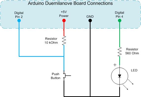
On the Duemilanove, there are 2 hardware interrupts available. These are located on Digital Pins 2 and 3. In this demo, we will use Pin 2, and also use Digital Pin 4 as an output to control an LED. The schematic for this is shown below;
Standard Digital Input and Output - No Interrupts
If you set up the Arduino as per the schematic and upload the code below to the microprocessor. Here you read the value of an input, do a conditional comparison, run some lengthy routine and repeat.
This will given unpredictable outputs on the LED due to the lengthy process being at an undetermined point in relation to when the input button is triggered. Sometimes the LED will change state immediately, other times nothing happens, and then sometimes you need to hold the button for a while for the state changed to be recognised.
This will given unpredictable outputs on the LED due to the lengthy process being at an undetermined point in relation to when the input button is triggered. Sometimes the LED will change state immediately, other times nothing happens, and then sometimes you need to hold the button for a while for the state changed to be recognised.
Making Use of Interrupts
Now we will use the same schematic diagram and modify the code to make use of hardware interrupts. Now when you upload the code, the LED changes state whenever the button is pressed. Even though the code is still running the same long delay in the main loop.
The
volatile keyword is added to the state variable, this causes the compiler to use RAM instead of a storage register. This is done because the storage register can be temporarily inaccurate if they are being modified by areas other than the main thread. In the Arduino, this relates to code being triggered by interrupts.The
attachInterrupt(param1, param2, param3) requires 3 parameters, these are;param1 = Which interrupt to listen for. This is the Interrupt Number not the Digital In number
param2 = Which code function to call, this must be a method that takes no parameters and returns no value.
param3 = Which condition to watch for.
The Arduino can listen for 4 types of condition changes. These are;
LOW = The input is at a LOW state
RISING = The input state changes from LOW to HIGH
FALLING = the input state changes from HIGH to LOW
CHANGE = The input state changed from HIGH to LOW or LOW to HIGH, i.e. has changed its state
ReAssigning Interrupts
Interrupts can be changed at any point by using the
attachInterrupt() method. As soon as this is done, any previously assigned interrupt on the associated pin is removed.
Starting / Stopping Interrupts
The Arduino also has the ability to temporarily ignore all the interrupts. You may want to do this if you have some sensitive code that must be executed without interruption. In this case you would issue a
noInterrupts() call. Once your sensitive code block has completed, interrupts can be restarted by calling interrupts().
Removing Interrupts
Interrupts can also be removed by using the
detachInterrupt(interrupt_number) method.
So, that is it, a quick basic introduction to hardware Interrupts on the Arduino platform. Now, you just need to see how they fit in with your projects, and how you can make use of them.

Comments
Post a Comment